Korzystasz z poprzedniej wersji strony – zapraszamy na nową odsłonę satel.pl!
You're browsing the previous version of this website. Go to satel.pl/en/ and see how we've changed!

Brand new INT-TSH2 and INT-TSG2
touchscreen keypads

Powerful processor, completely new interface,
swipe gestures support.
Meet the new level
of safety and building automation control.

Register for a free online course now

Choose a topic and learn with SATEL technical specialists.
For professional installers only.

CONFX hardware configurator

New version now available!

  • Even more useful functions
  • Easier and faster designing
  • New appearance

SMART BUILDING solutions

KNX modules

now available in SATEL's offer!

Find out more

SATEL on YouTube and Vimeo

Over 30 films and animations about us and our products

- subscribe to our channels and stay up to date!


ACSP-402

Fire alarm control panel

The ACSP-402 fire alarm control panel is designed to:

  • monitor operation of automatic and manual call points,
  • control sirens,
  • control devices used to transmit fire alarms and failure signals
  • control the operation of fire protection devices or systems,
  • monitor the operation of fire protection devices or systems,
  • monitor the operation of other external devices,
  • control other external devices

These features make it possible to detect a fire at its earlies stage and alert the users of the building with acoustic and/or optical signals as well as notify relevant services. This in turn allows one to quickly commence fire-fighting activities. The control panel can also automatically activate fire protection devices.


System structure

  • support for up to 256 zones
  • support for up to 32 groups
  • possibility to create interlinks between zones, sub-zones and groups
  • support for up to 256 call points (detectors / MCPs)
  • support for addressable detection circuits of the following types:
    • loop (up to 2 circuits)
    • radial line (up to 4 circuits)
    • loop with a side line / side lines
  • support for a printer
  • extensive functions for testing the control panel and system

Inputs

  • 4 programmable inputs on the control panel mainboard (NO, NC)
  • monitoring of external devices status, e.g. for reporting fire alarms and failures

Outputs

  • 2 control outputs for conventional sirens
  • control output for fire alarm transmission devices
  • control output for fault signal transmission devices
  • 8 programmable relay outputs
    • control of external devices
    • output for controlling automatic fire protection equipment
  • 24 V DC power supply output
  • dedicated power supply output for ACSP-ETH and ACSP-RSI modules
  • signal delay at outputs

RS-485 communication buses

  • 2 bus ports for connecting
    • APSP-402 repeater panel
    • ACSP-ETH module (for extending the control panel with an Ethernet port)
    • ACSP-RSI module (for opto-isolation of the bus and connection of a printer)

E-mail notification (requires connecting the ACSP-ETH module)

  • 4 addresses for notification
  • selection of event types for notification
  • periodic diagnostic reports

Setting up

  • setting up with keys on the front panel of the control panel
  • free ACSP Soft programme for configuring the control panel (USB port)

Event memory

  • non-volatile memory for up to 9999 fire alarms
  • non-volatile memory for 8999 events (including fire alarms)

Control panel mainboard module

  • LEDs for signalling the status of the control panel and external devices
  • LCD display for:
    • setting up the control panel
    • presenting information about fire alarm
    • presenting information about disablement, test or failure conditions
    • viewing the list of current disablement, test or failure conditions
    • viewing the history of alarms and other events
  • USB port to connect a computer
  • power supply connection
  • battery connection
  • built-in piezo transducer for acoustic signalling
  • real-time clock with battery back-up power

Power supply

  • switching mode power supply APS-318 with short circuit protection
  • automatic switching to back-up power supply (battery) in case of failure of the main power supply
  • battery charging circuit with temperature-compensated charging voltage
  • monitoring of the battery status and disconnection of a flat battery
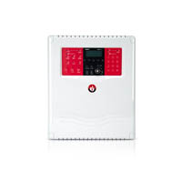
ACSP-402
The actual appearance of the products may differ from the presented images. Product descriptions are provided in the web service for information purposes only.

Documentation

user manual
updated: 2023-06-27
953 KB
programming
updated: 2023-06-27
792 KB
installer manual
updated: 2023-05-22
2.34 MB
mounting template
updated: 2023-03-06
924 KB

Software

Polish, English, French, Dutch, Spanish, German, Portuguese, Russian, Slovak, Hungarian
compiled: 2023-04-19
English
compiled: 2018-10-23
English
compiled: 2024-03-11
multi-language
compiled: 2024-03-19
135 MB

Certificates

Declaration of performance
updated: 2023-03-15
973 KB
Other certificates
updated: 2023-05-18
3.01 MB

Technical Data

Operating temperature range
-5…+40°C
Supply voltage (±15%)
230 V AC, 50-60 Hz
Maximum humidity
93±3%
Dimensions
324 x 382 x 108 mm
Maximum current consumption from the 230V network
300 mA
Transit temperature range
-25…+55°C
Operating duration of the stand-by supply
72 h
Maximum internal apparent resistance of the battery (with cables and terminals in a circuit)
1,1±10% Ω
Current draw from the battery when detecting
220 mA
Current draw from the battery when emitting an alarm
320 mA
Current draw from an integrated AC power adapter when detecting
200 mA
Current draw from an integrated AC power adapter when emitting an alarm
300 mA
Sealing of the casing
IP30
Events storage capacity
8999
Alarm counter capacity
9999
Delay time of alarm transmission to the outside
0...10 min
Clock battery
3 V (CR2032)
Output for communication with PC (service output)
USB typ B
Terminating resistor on terminals for communication with the remote panel
100 Ω
Output for communication with remote panel and CSP-ETH module
transmisja szeregowa
Supply output +24V
24 V DC±15%
Supply output AUX (only for connecting CSP-ETH module): in standard mode
18 V DC +5%, -15%
Alarm resistor on the control input circuit
1 kΩ±5%
Terminating resistor on the control input circuit
10 kΩ±5%
Number of programmable control inputs
4
Electrical parameters of relay outputs
1A / 30 V DC (NO or NC)
Number of alarm transmission circuits
1
Working voltage of the alarm transmission circuit
24 V DC±15%
Maximum current of the alarm transmission circuit
180 mA
Terminating resistor on the alarm transmission circuit
10 kΩ±5%
Number of fault transmission circuits
1
Working voltage of the fault transmission
24 V DC±15%
Maximum current of the fault transmission circuit
180 mA
Terminating resistor on the fault transmission circuit
10 kΩ±5%
Number of programmable relay outputs
8
Stand-by supply: internal acid battery
12 V / 17 Ah
Stand-by supply: external acid battery
12 V / ≤33 Ah
Supply output AUX (only for connection of CSP-ETH module): with AC power supply failure
12 V DC +15%, -20%
Maximum battery charging current
1,4 A
Overcurrent protection of the power supply unit (time-delay fuse)
3,15 A
Current parameters of the integrated power supply (acc. to EN54-4) - Imax a
1,6 A
Current parameters of the integrated power supply (acc. to EN54-4) - Imax b
1,6 A
Battery charging system overcurrent protection (time-delay fuse)
3,5 A
Maximum number of addressable detection circuits (loop)
2
Maximum number of addressable detection circuits (radial line)
4
Maximum resistance of the addressable detection circuit
100 (2 x 50) Ω
Maximum number of line elements in an addressable detection circuit
128
Maximum number of line elements in an addressable detection circuit of the radial line type
32
Maximum number of automatic call points in a conventional detection circuit
32
Maximum number of manual call points (ROPs) in a conventional detection circuit
10
Maximum current in a detection circuit
200 mA
Maximum resistance of the circuit for alarm and fault signalling devices
75 (2 x 37,5) Ω
Number of external circuits for signalling devices
2
Operating voltage of conventional alarm circuits (±15%)
24 VDC
Maximum current of the circuits for conventional signalling devices
180 mA
Terminating resistor on the conventional signalling devices circuit
10 kΩ±5%
Load capacity of the +24 V supply output
200 mA
Weight without the battery
2721 g

Information materials

3leaflet - installer

5product data sheet

 © 1990-2021 SATEL sp. z o.o.
legal | privacy policy | Feedback | about site

The Satel.pl website uses cookies to enable Users' to take advantage of Satel.pl features as well as for statistical purposes. Unless you block cookies, you grant your consent for their use and storage in device memory. You must remember that you are able to manage cookies by means of your browser settings. Lack of adjustment of these settings means your consent for the Satel.pl website to use the cookies. See our Privacy Policy for more information.

Zamknij